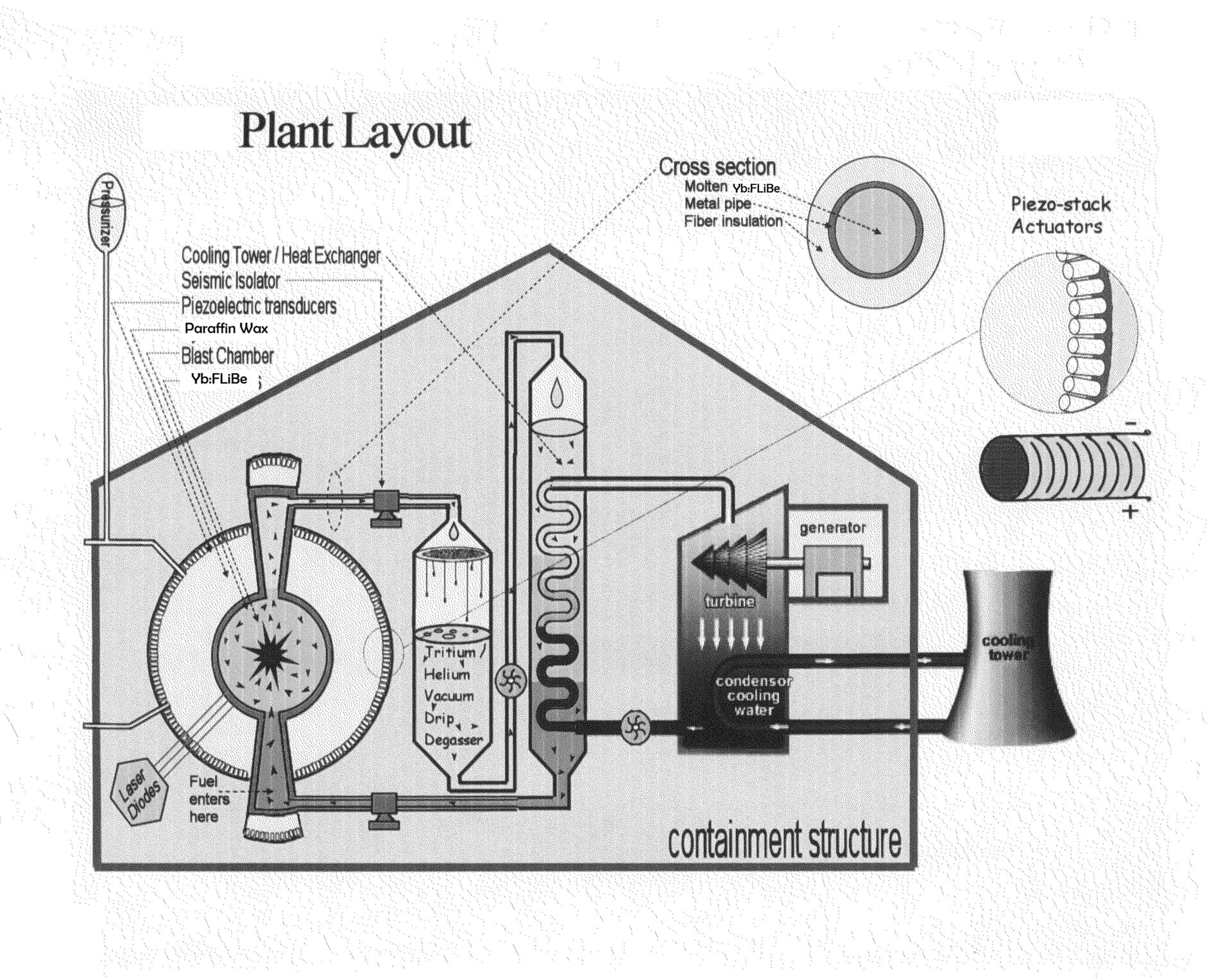
A nuclear fusion power plant having a spherical blast-chamber filled with a liquid coolant that breeds tritium, absorbs neutrons, and functions as both an acoustical and laser medium. Fuel bubbles up through the sphere’s base and is positioned using computer guided piezoelectric transducers that are located outside the blast-chamber. These generate phase-shifted standing-waves that tractor the bubble to the center. Once there, powerful acoustic compression waves are launched. Shortly before these reach the fuel, an intense burst of light is pumped into the sphere, making the liquid laser-active. When the shockwaves arrive, the fuel temperature skyrockets and it radiates brightly. This, photon-burst, seeds outgoing laser cascades that return, greatly amplified, from the sphere’s polished innards. Trapped within a reflecting sphere, squeezed on all sides by high-density matter, the fuel cannot cool or disassemble before thorough combustion. The blast’s kinetic energy is absorbed piezoelectrically.
A power balance relationship exists between the heat gained by fusion alpha-particles and that lost due to Bremsstrahlung cooling. Self-heating and ignition take place when the temperature exceeds this balancing point (the red dots, in FIG. 12). For ICF, the ideal ignition temperature is 4.3 keV. In comparison, BSF ignites at 1.6 keV. The reason they differ by so much is because BSF prevents radiant losses. It does this by surrounding the fuel with an imploding wall of opaque (to x-ray) coolant. Whatever radiant energy makes it through the coolant gets reflected by the spherical cavity mirror and reabsorbed back into the fuel. The idea behind Radiant Energy Reabsorption is to slow losses down enough so that self-heating can cause an accumulation that leads, through positive feedback, to an eventual ignition.
FIG. 3 is a cut-away view showing how the metal sphere is situated inside of the piezoelectric sphere, and where the spiral detectors are located. It also shows several modular laser pumps and the fiber optic cables associated with them. In an actual reactor there would be more fiber optic cables, probably around one thousand, and each module would contain a single stacked laser diode array and photo-detection and control circuitry. The modules would connect to fiberoptic cables so they could transmit their laser output to the inside of the metal sphere. It might be possible to power these modules locally by using energy harvested piezoelectrically. The cables (fiber optic bundles) depicted are not to scale, as they are only estimated to be about one inch in diameter. Cable attachments made to the sphere’s surface must be able to withstand tremendous stresses. One way to cope with the stress is to have the ends of the fiberoptic cables fused so that they would form durable silica plugs that could be inserted into the shafts that were drilled to let light in/out of the sphere. The ends of the cables could then be attached to the outside of the sphere using springs that would allow the plugs to function like shock absorbing pistons. This gives the connecting parts some flexure, and minimizes the jarring stress and strain that would otherwise interfere with and inhibit the sphere’s natural resonance. Also shown are the large cone-shaped pipes that lead into and out from the sphere. These function as low-speed settling chambers, reducing turbulence and making the flow more laminar.
FIG. 10 shows the F-crosssection of FIG. 9 (dotted box), and how multiple vertical linear sensor arrays (VLSAs) can be combined. Each VLSA has a narrow field-of-view, taken from a specific viewing angle. These views combine, overlapping in the center, so that even if a bubble of fuel is not in the exact center of a vertically rising FLiBe column, it will still be likely to detect it by at least one of these arrays. In addition, having multiple arrays increases both the sensor resolution and the maximum rate of laser pumping.
FIG. 11 shows how the four different parameters (fuel size, fuel offset from the center, number of reflections, and mirror surface quality) effect the amount of radiant energy that gets reabsorbed by a hot radiating bubble of fuel located within a 5 meter radius reflective silver-plated sphere. The charts are arranged in a 3×3 array, to show that increasing the mirror surface quality increases the total amount of reabsorption and that, contrary to common sense, the probability of absorption immediately following the second reflection is several times higher than the absorption following the first reflection.
An observation worthy of attention, is the fact that, because of spherical geometry, a ray of light inside the sphere has its path confined, bouncing on a single plane that it cannot leave. That plane is determined by the ray’s origin, the first point of reflection, and the sphere’s center. A close examination reveals that if a ray of light passes close to the center it will return after two reflections, revisiting the same approximate location. This observation appears prominently in the simulation results (FIG. 11), which show an unexpectedly high two-reflection reabsorption rate. This (high two-reflection reabsorption rate) improves the sphere’s overall energy retention ability, allowing off-center target ignition. Also, since there is extra leeway to position the fuel, a less stringent control system is required.
FIG. 5 a graph comparing total lithium volume requirements for three types of fusion reactors.
FIG. 6 shows the Archimedean Spiral Array which is made from two thick metal plates that have a pattern of holes drilled into them. The plates are located at the top and bottom of the reactor. The tiny black dots in the figure are the apertures of holes where the end of a fiberoptic filament protrudes. Each fiber leads back to circuitry that can generate and/or detect optical pulses traveling between opposite plates.
FIG. 7 is a graph showing the reflectivity of different mirror elements vs. electromagnetic frequency. This information was used when running computer simulations of the optical conditions found inside the sphere after a gold (Au) or silver (Ag) electroplate was applied.
FIG. 16 This is an example of a graph showing bubble size vs. rate of ascent.
FIG. 17 shows that pressure gradients control the direction of a bubble’s movement. It also shows that the background pressure controls the bubble’s size, which indirectly controls the bubble’s speed.
FIG. 18 shows the expected blackbody radiation spectrums for a range of plausible coolant and bubble temperatures. The values plotted were calculated using Planck’s equation, Pλ=2πhc2/λ5(ehc/λkT−1), in standard SI units, and divided by 1013 to convert for (W/m2 per m) into (W/cm2 per nm). This graph is important to BSF for two reasons. First, it shows that the amount of blackbody radiation (which corresponds to the coolant temperature) inside the laser cavity is not significant toward triggering laser amplification, since the intensity of blackbody radiation occurring at the laser frequency is much less than the lasing threshold. Second, it shows that temperatures inside the compressed bubble would be sufficiently hot to cause a significant levels of blackbody radiation at the laser frequency, enough to trigger a laser amplification cascade.
FIG. 23 is a chart constructed using simulation data for a 5 meter silver-plated (92% reflectivity) sphere. It is based on the fraction of light that returns to the fuel after two bounces when the inside surface of the metal sphere has a “MEDIUM” surface quality finish. Each bar of this 60 bar chart corresponds to a 50,000 trial Monte Carlo simulation. Each trial tracks one randomly directed ray of light coming from a random location on the fuel’s surface, and follows it until it gets absorbed (by either the mirror or fuel) or times-out. Each time the ray encounters the mirror’s surface, a random number is generated to determine the chance of it being absorbed and/or how much deviation to add to the ray’s angle of reflection.
FIG. 24 is a graph showing the relationship between the incident laser intensity and the fraction of light that is absorbed by the fuel for a variety of wavelengths. The most interesting trend is that absorption increases with decreasing laser intensity, so that a long, low-intensity pulse would be the most efficient method of supplying energy to the target.
Whoa! This is wild and awesome! You’re using the same fluid for cooling, tritium breeding, and LASING? And you’re moving fuel bubbles with acoustic tractor beams?! That’s bananas - in a good way! I love how it all works together like a little fusion symphony!
Raw energy numbers can be misleading. Chemical explosives convert nearly all their energy into hot, dense gases that push outward, generating intense blast pressure. In contrast, DT fusion releases about 80% of its energy as high-energy neutrons that penetrate deep into the surrounding blanket, where the energy becomes heat—not pressure. Only a tiny fraction contributes to a shock wave. So despite having the same total energy as ~1000 sticks of dynamite, a small DT fusion burst produces nowhere near the same physical destruction.
A 3 mg DT burst packs the energy of ~1000 sticks of dynamite, but ejects eight orders of magnitude less mass. Since momentum scales with the square root of mass, dynamite is ~40,000 times better at delivering a shove - and it’s that shove, not heat, that wrecks buildings and flips cars.
This means BSF can operate safely with higher yields - good news:
Yields from ICF targets increase super-linearly with the amount of driver energy. Ideally, to maximize gain, the reactor should operate at the highest yield it can tolerate, even if that means a lower repetition rate. For instance, Sandia National Laboratories proposed 20 GJ targets in their 2005 annual report for a cylindrical Z-IFE chamber (6 m radius, 8 m height) running at 0.1 Hz to produce 2000 MW. Their reasoning: “The economics of scale will favor having a single chamber with the largest acceptable yield.” A lower repetition rate also simplifies pumping the hot blanket material between pulses.
This seems like a Rube Goldberg machine. Combining four complex roles into one exotic fluid introduces failure modes at every step. A simpler path, with less interdependencies, is more likely to succeed.
Instead of relying on an acoustic tractor beam for fuel transport, the fuel could be encapsulated at one end of a rod made from solidified coolant of sufficient length to span the width of the reactor. In this form, it could then be inserted directly into the sphere, like a large artillery shell being rammed into a gun’s firing chamber. Another way of getting fuel to the center is by controlling the 3-dimensional flow of coolant inside of the sphere, using valves that regulate the flow coming from multiple inlets and going to multiple outlets. In this scenario the fuel would bubble up from the base of the sphere and be carried along with some quantity of displaced coolant.